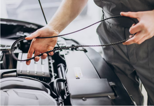
In motorsport, electrical reliability is measured in more than component life. A cable fault that takes twenty minutes to locate can cost a practice session or delay critical setup work. Harnesses must therefore survive heat, vibration and tight packaging while remaining easy to inspect and replace under pressure.
Designing trackside-ready Motorsport Cables means considering maintenance from the start. Routing, connector location, labelling and modularity all influence how quickly a team can isolate a problem between sessions.
Design Around Service Points
A harness should not be treated as one uninterrupted assembly. Engineers should identify areas exposed to repeated movement, high temperatures, fluids or frequent disconnection. Connector interfaces and terminations are especially important because sustained vibration can create micro-movement and fatigue. GEM Cable notes that engine vibration, chassis flex and kerb strikes generate cyclic loading across motorsport harnesses.
Service points should sit near components that are likely to be removed. This allows technicians to change a sensor, module or branch without disturbing the complete loom.
Use Modular Sections Selectively
A fully integrated loom may reduce connector numbers, but it can make repairs slower. If a damaged branch cannot be separated, the team may need to remove a much larger section of wiring.
Modular construction can divide the system into practical zones, such as:
- Engine and powertrain
- Cockpit and controls
- Data acquisition
- Front and rear chassis sections
Every breakpoint should have a clear purpose. Too many connectors add weight and additional failure points, so modularity should be used where it genuinely improves access, diagnosis or replacement.
Keep Connectors Accessible
Connectors hidden behind panels or tightly packed components can turn a simple check into a lengthy strip-down. Where packaging allows, they should be positioned so technicians can inspect locking features, backshells and strain relief without removing unrelated parts.
Robust housings and backshells help protect terminations from shock, vibration and excessive bending. TE Connectivity describes backshells as providing cable support and strain relief that can prevent overflexing at connector exits.
Accessibility should not compromise protection. Connectors still need to be positioned away from excessive heat, water, debris and impact.
Build Clear Identification Into the Loom
Trackside diagnosis depends on certainty. Technicians should be able to identify a branch without tracing it through the entire vehicle.
A practical identification system may include:
- Durable wire and connector labels
- Consistent circuit names
- Colour or sleeve coding
- Matching references on drawings
Labels must remain legible after heat exposure, cleaning and repeated handling. The same reference should appear on harness drawings, test records and vehicle documentation so that design and trackside teams use one system.
Protect Without Hiding Problems
Sleeving and heat-shrink tubing can protect wires against abrasion, chemicals and heat while supporting strain relief around splices and connector transitions.
Protection should not make inspection impossible. Critical breakouts and backshells need enough visibility for technicians to spot movement, contamination or damage. Routing should also avoid sharp edges and unsupported spans. Motorsport UK guidance states that wiring should be secured and protected to reduce the risk of short circuits.
Involve the Manufacturer Early
Experienced Cable harness manufacturers can add the most value before vehicle packaging and connector schedules are finalised. Early collaboration allows routing, breakout positions, bend limits and service access to be reviewed before production.
A detailed drawing should show individual wire routes, branch points and terminations. GEM Cable explains that harness assembly drawings define how wires travel between endpoints and where they separate from the main bundle.
Prototype builds can reveal inaccessible connectors, excessive tension or branches that interfere with other components. Correcting these problems before repeat production reduces later modification work.
See also: Google Analytics vs an SEO Reporting Dashboard: Why Businesses Need Both
Test the Replacement Process
Electrical continuity testing confirms correct assembly, but trackside readiness also needs practical testing. Teams should rehearse access to common service points and record how long it takes to isolate and replace a section.
The review should check whether tools can reach connectors, labels are visible and removal can be completed without disturbing nearby wiring. Technician feedback should inform the next harness revision.
Conclusion
A reliable motorsport harness must do more than carry power and data. It should support rapid inspection, clear diagnosis and controlled replacement when track time is limited. Modular sections, accessible connectors, durable identification and carefully selected protection can reduce time lost to electrical faults.
The strongest results come from designing maintenance into the harness rather than treating it as an afterthought. Early collaboration between engineers, technicians and manufacturing specialists creates a system better prepared for demanding race conditions and the realities of trackside repair.


